Case 01 / BU EK210 Section A9
Optical communication prototype
Transmit keyboard-entered text over a directional optical link, with a 5 ft minimum distance requirement.
My contribution
Contributed to CAD, integration and testing (owner-reported). Specific subsystem decisions remain unresolved; printed-part manufacture is credited to Jake Spaulding.
Key result
The team reported transmission through 13 ft against a 5 ft requirement. Raw trial counts and complete conditions are unavailable; this does not establish guaranteed range or an error rate.
Results and technical detail ↓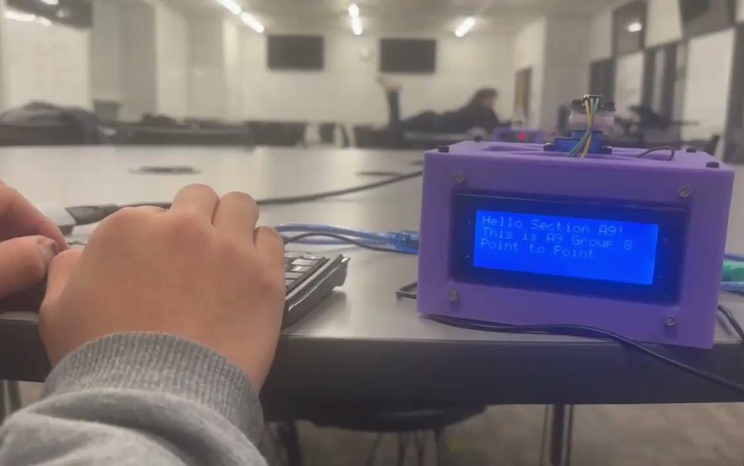 View full size
Constraints
- Distance requirement and component budget documented in team report.
Implementation and Evidence
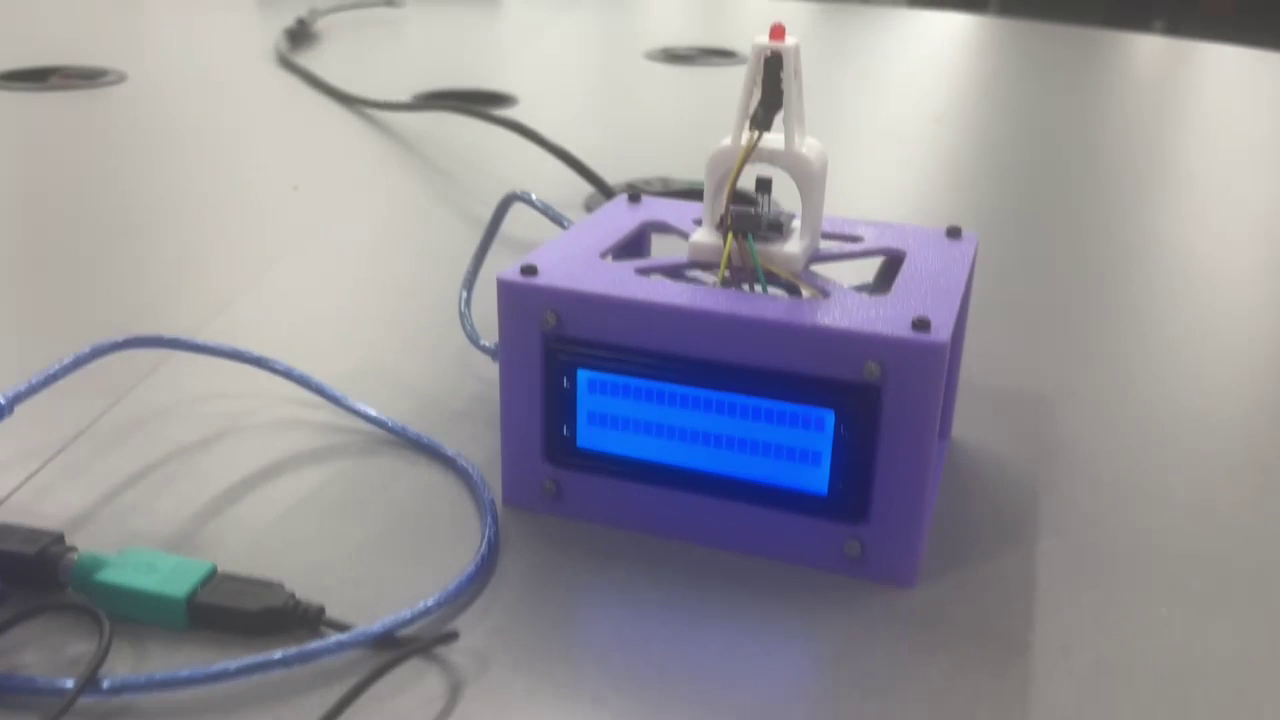
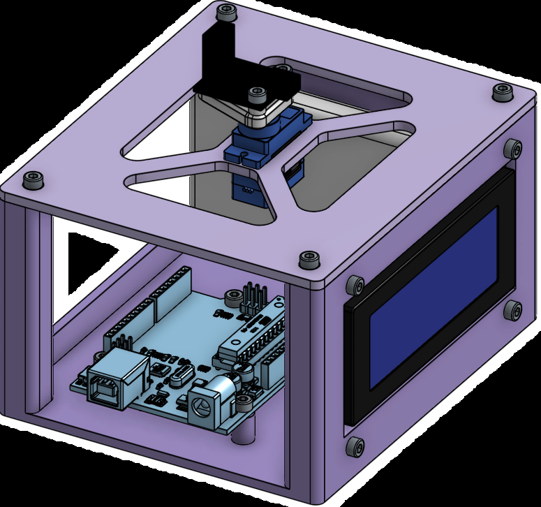
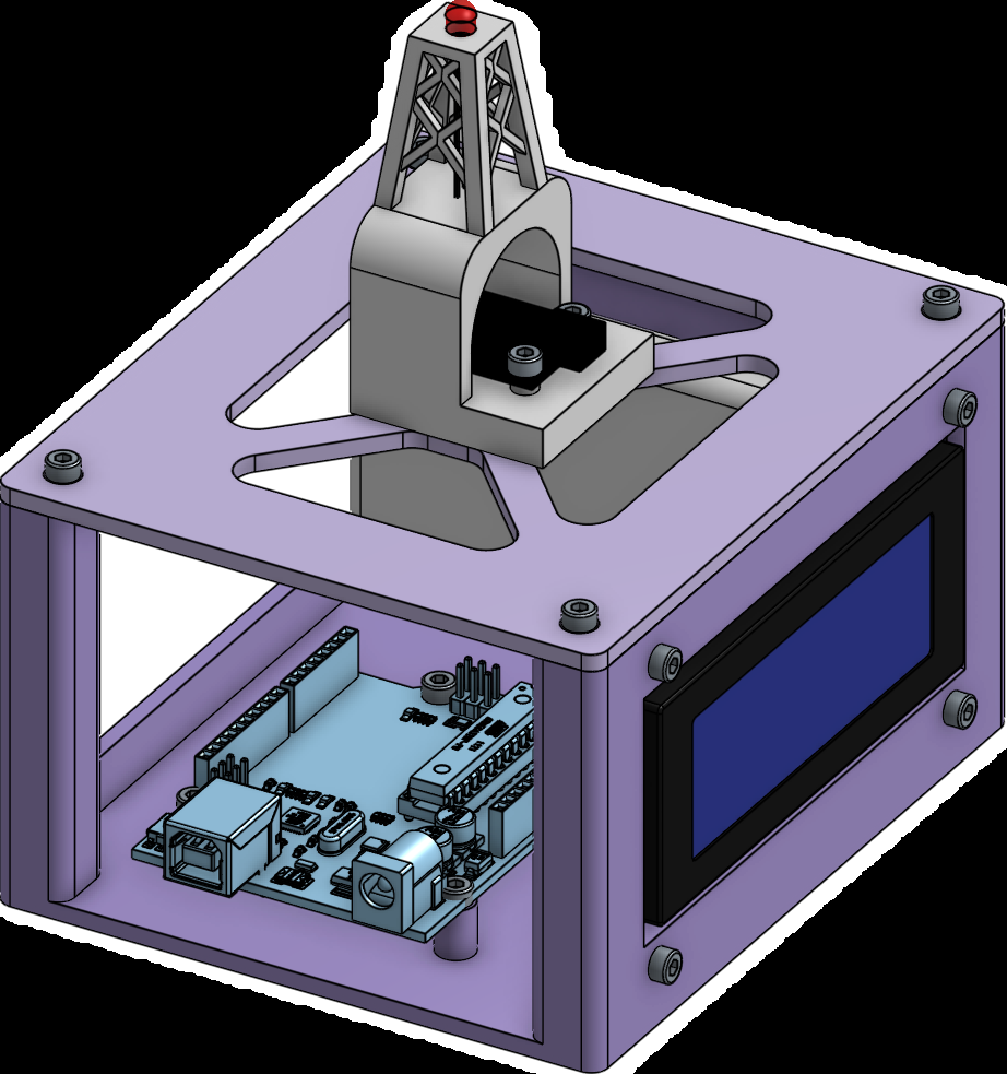
Printed enclosures organize electronics, display access and optical aiming. The team CAD shows an optical mount above the lid and electronics below; the prototype photograph shows the packaged system.
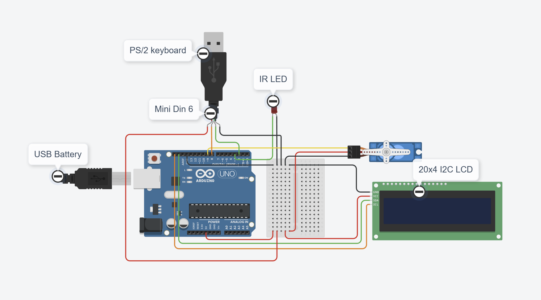
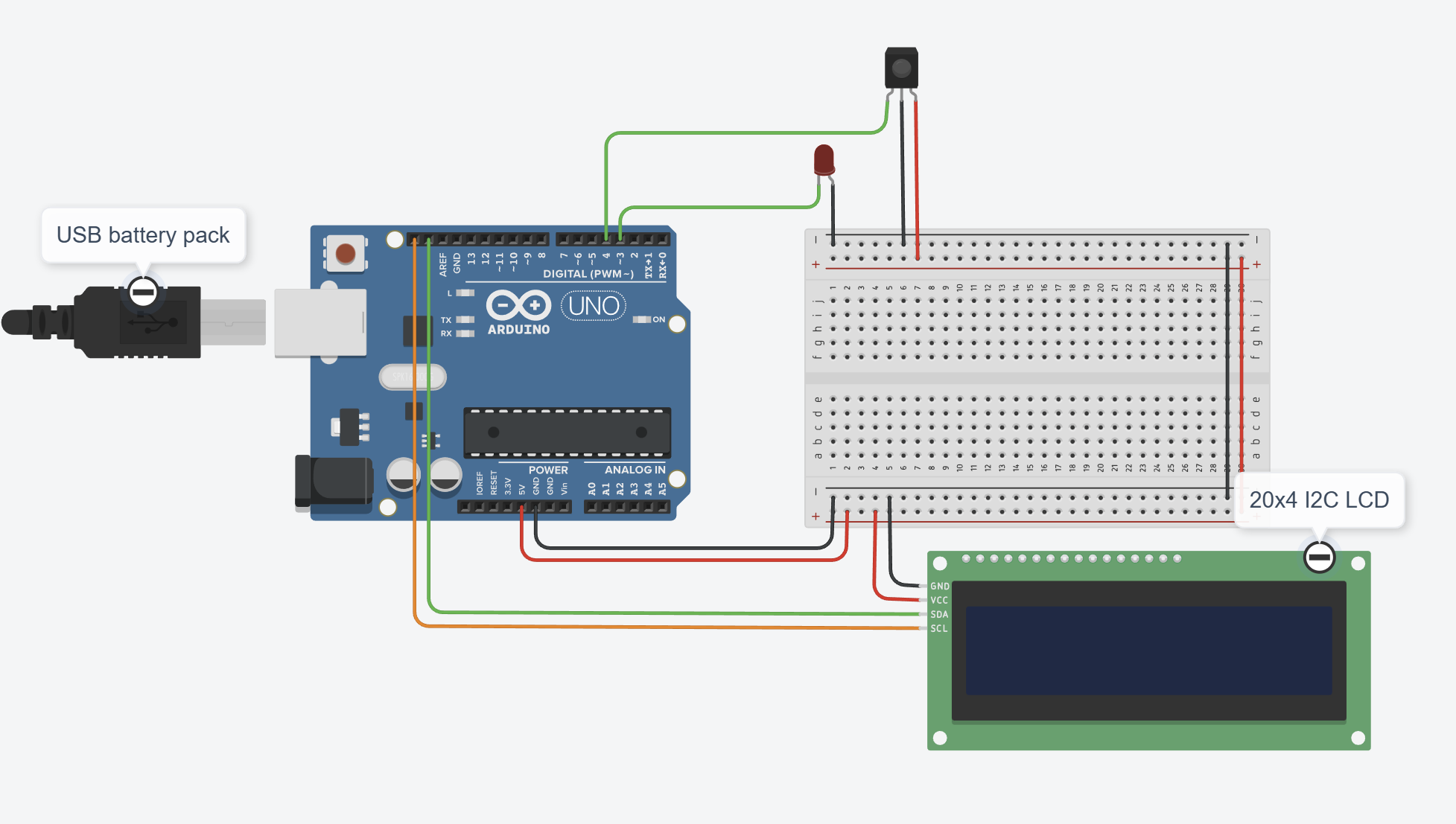
The documented path connects PS/2 keyboard input to Arduino, 38 kHz IR modulation and receiver LCD output, with servo aiming. The carrier frequency is not data throughput. Alignment and ambient light remain important unrecorded test conditions.
 View full size
 View full size
 View full size
 View full size
 View full size
Evidence & interpretation
Results & validation
The team reported transmission through 13 ft against a 5 ft requirement. Raw trial counts and complete conditions are unavailable; this does not establish guaranteed range or an error rate.
Team prototype integrates Arduino, PS/2 input, IR modulation, LCDs and servo aiming.
verified-in-artifact · teamIR modulation
38 kHz
verified-in-artifactModulation frequency; not data throughput.
Distance requirement
5 ft
verified-in-artifactCourse/team requirement, not an achieved test measurement.
Reported transmission range
13 ft
qualified team-reported resultRaw counts, trial independence, message length, ambient lighting and alignment protocol unavailable; no every-attempt or field-reliability claim.
Component BOM · TX / RX / total
86.51 / 45.85 / 132.36 USD
reported estimateListed transmitter, receiver and combined BOM; reported component costs, not receipts, current procurement or production cost.
Transmitter budget · typical / max
1.98 / 3.65 W
reported estimateEstimated typical and maximum transmitter component budgets; not measured system draw.
Receiver budget · typical / max
1.46 / 2.225 W
reported estimateEstimated typical and maximum receiver component budgets; not measured system draw.
Engineering limitations
Range is team-reported without raw counts or complete test conditions. Power budgets are component estimates, not measurements. Printed-part manufacture is credited to a teammate.